
SERVO STABILIZER (AIR COOLED) UP TO 4000KVA
The Issue
Electricity is perhaps the most essential raw material used by commerce and industry today. The electricity produced in power plants is circulated through the electricity transmission and distribution networks and it is supplied/delivered to consumers; the quality of electricity (known as «Power Quality») is one of the important factors that determine the economic efficiency of both consumers and electrical networks.
Electrical devices are designed to work in distributing systems defined by set nominal values in terms of voltage and frequency (for example, 400V at 50Hz).
In actual fact, electric energy distribution might not ensure the stability of said nominal parameters. Voltage in particular can vary even considerably in relation to the nominal value. These variations can cause undesired and potentially dangerous conditions for the users.
The continuous availability of stable voltage supply independently from input fluctuation is very often a key feature to ensure efficiency and reliability for the User.
Reduced productivity, data loss, security failure, machine faults, inaccurate information and domestic inconveniences are only a few examples of potential problems caused by unsteady supply. Obviously, all that results in higher managing cost.
The Solution
The voltage stabilizer has proven to be an effective solution able to prevent potentially dangerous situations created by input voltage instability.
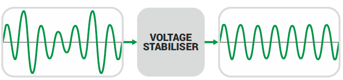
A voltage stabilizer is a power device destined to be positioned between the mains and the User. The purpose is to ensure that the User is fed a voltage subject to a variation of ±1%.
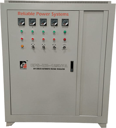
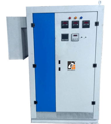
The voltage regulator is nothing but an auto transformer with continuously variable transformer ratio. The Stabilizers are built in an IP21 metallic enclosure dully painted. Cooling is guaranteed by natural air circulation aided by extracting fans over a certain temperature.
Working principle of an electro–mechanical digital voltage stabilizer.
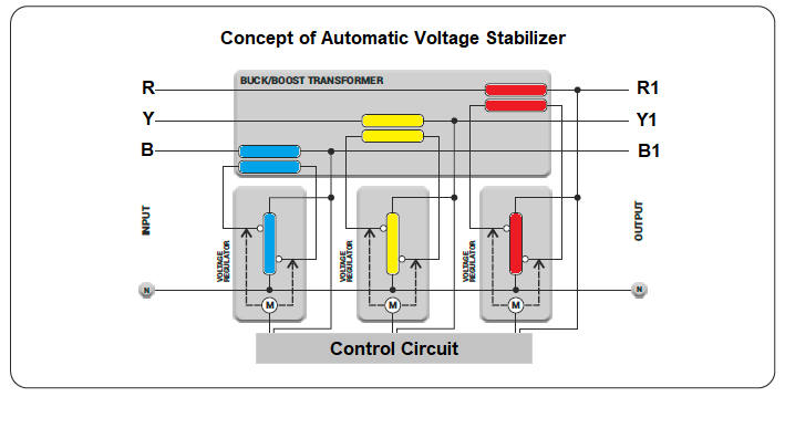
Main Components
1. Buck/boost transformer: –
Often referred to as ‘booster’ transformer, it is a standard dry-type transformer with the secondary winding connected in series to the mains and the primary winding supplied by the voltage regulator.
2. Voltage regulator: –
Basically, it is an autotransformer with continuously variable transformer ratio. The voltage intake varies depending on the position of the rolling contacts; therefore the voltage supplied to the booster transformer primary winding also varies. Being the voltage across the regulator contacts (and consequently that on the secondary winding of the booster transformer) either in phase or in opposition to the supply voltage, it is then added or subtracted to the supply voltage, thus compensating its variations.
3. Auxiliary circuit with microprocessor: –
The DSP (Digital Signal Processor) microprocessor-based control circuit (specifically designed for drives with totally digitalized signal) compares the output voltage value to the reference one sampling it 2000 times per second.
When an anomaly is detected, the control drives the voltage regulator gear motor. By doing so, the regulator rollers change their position thus varying the voltage drawn and supplied to the buck/boost transformer primary winding. The input voltage variation is therefore automatically compensated. The control system operates so that the output accuracy is ±0.5%. The microprocessor is fitted with the soft stop function enabling a precise positioning of the regulator rollers regulation to work smoothly even in case of strong fluctuation of the input voltage.