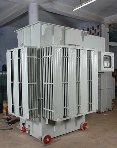

SERVO VOLTAGE STABILIZER (OIL COOLED)
THE CONSTRUCTION PROCESS
At the heart of the Voltage Stabilizer are the regulator coils. While some small capacity regulator coils are uncompensated, all larger capacity voltage stabilizer regulator are fully compensated.
Compensation is a method where by the naturally high reactance of long thin coils, used in the construction of the ‘Reliable’ Regulator coil is limited to a low value across the range of variation.
Limiting the reactance tends to produce a linear variation in the output voltage of the regulator, across the range of operation. Contact pick up tracks are machined onto the faces of the coils. Depending on the required output arrangement there may be tracks on both sides of the coil, or only on one side.
The coils are then mounted on a core of grain oriented silicon steel laminations.
The core and coils are mounted in a steel framework that allows roller contacts to be presented to the coil faces at a constant pressure across the range of operation.
To achieve variation in the output voltage the roller contacts are moved along the coil face. Roller contacts are housed within retaining assemblies that are in turn fixed to a carrier board. The carrier board’s position is maintained by a chain drive system that is in turn attached to the drive mechanism, either hand- or motor-driven.
Cooling
The construction of the ‘Reliable’ Regulator assembly allows the same basic unit, with only minor changes, to be used either immersed in cooling fluid, or directly air-cooled.
For the larger power ratings of regulator, fluid immersion is used exclusively.
Output
Due to the flexibility of the design several arrangements can be provided. These range through single phase or three phase to double output for buck boost arrangements where the output of the regulator starts at a maximum voltage, decreases to zero, and then again increases in voltage but with the polarity reversed.
Buck boost connection is used where the minimum output voltage is above zero volts. Basically the connection comprises of two fixed ratio transformers and a double output voltage regulator.
One fixed ratio transformer (commonly referred to as the Main Transformer) has an output voltage approximating to the mid-point of the range required. The second fixed ratio transformer (commonly referred to as the Buck Boost Transformer) has an output voltage approximating to the difference between mid-point, and minimum / maximum required voltage, and there output windings are connected in series. The input winding of the buck boost transformer is connected across the two outputs of the regulator.
With the roller contacts located at one end of the regulator a maximum voltage at a specific phase relationship to that of the fixed ratio transformers is produced.
The transformers are arranged so that in this condition the output voltage of the buck boost transformer is subtracted from the output voltage of the main transformer.
This provides the minimum output voltage of the arrangement.
As the roller contacts are moved to the centre of the regulator the output voltage of the regulator, and hence the buck boost transformer approximates to zero. The combined output of the arrangement is therefore the output voltage of the main transformer.
Continuing to move the roller contact in the same direction will increase the regulator output voltage. In addition the polarity of the voltage will have reversed so that the output voltage of the buck boost transformer is now added to that of the main transformer. By this means the maximum output voltage of the combination is achieved.
Duty
The ‘Reliable’ Regulator has good short term overload capacities. The equipments are designed for 100%duty cycle.
Almost any duty can be catered for. If you have specific requirements that you wish to discuss please contact our sales force.
Control
The units are designed for Standard Input Voltage Ranges as under
| Input Voltage | 360-450V | 350-460V | 340-460V | 320-460V | 300-460V | 280-460V | 260-460V | 240-460V |
| Efficiency (as calculated with tolerance) | 99.60% | 99.50% | 99.35% | 99.00% | 98.70% | 98.20% | 97.60% | 97.20% |
Technical Advantages
- Low Replacement Cost.
- Undistorted output characteristics ie. no wave from distortion.
- Moving parts on L.T. side and it’s mass is extremely low, only few Ib-inch torque.
- Energy Saving from 5-10% depending upon the voltage variation and number of working hours.
- High efficiency (about 99%) and minimum no-load losses ± Simplicity and Flexibility of design.
- On Load Step less Voltage Variation with AUTO/SEMI/MANUAL Mode facility.
- Long Service Life of 15 -20 Years.
- Regulating coils are wound with rectangular conductors on their edge, thus giving high mechanical strength compared to other designs.
Applications of Voltage Regulators
Pharmaceutical Units, Cold Storages, Rolling Mills, Textile Mills, Paper Mills, Tube Mills, Rice Shellers, Rubber Industries, Food Processing Units, Oil & Vanaspati Plants, Footwear & Leather Units, Tea Gardens, Distilleries & Beverages, Hospitals & Nursing Home, Clubs, Hotels, High Rise Buildings, Furnace Transformers, Test Rooms, Glass Industries, Research Stations, Chemical Industries
The table below compares the behaviour of 5 H.P. motor at different voltage :-
| INPUTVOLTAGE | CURRENT | KVA | PF |
| 400 | 7.5 A | 5.2 | 0.8 |
| 425 | 11% More | 18% More | 0.7 |
| 435 | 19% More | 28% More | 0.61 |
| 445 | 265 more | 38% More | 0.57 |
The table below compares the behaviour of 60 watt lamp at different voltage :-
| VOLTAGE | CURRENT | WATTS | LUMINOUSINTENSITY | LIFE IN HOURS |
| 230 | 0.26 | 60 W | 710 | 1000 |
| 240 | 0.27 | 65 W-8.3% More | 820 | 575 |
| 250 | 0.28 | 70.6-17.6% More | 943 | 338 |
| 260 | 0.29 | 75.4-25.6% More | 1073 | 200 |
| 270 | 0.31 | 83.4-39% More | 1213 | 100 |